loading…
Glyph Gadget: a keychain-sized Nothing Glyph Matrix
Building V0 of a keychain gadget that recreates the Nothing Phone (3) and (4a) Pro Glyph Matrix on a tiny round display.
I have always liked how the Nothing Phone wears its Glyph Matrix on the outside. A grid of leds that lights up for calls, timers and music, sitting right there on the back of the phone. I wanted that same toy off the phone and in my pocket, so I built Glyph Gadget: a keychain-sized device that recreates the Glyph Matrix on a tiny round screen and plays the same dot animations you can design for the Nothing Phone (3) and the Phone (4a) Pro.
This is V0, a working prototype with real screws and a real battery, built to prove the idea. Here is how it came together, including the parts that did not work.
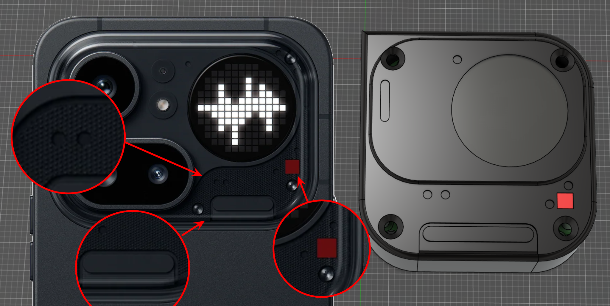 Design references from Phone (4a) Pro
The constraints
Before ordering anything I set three hard limits, and every later decision came back to them.
It had to be round, because the Glyph Matrix is round and a square screen would have missed the whole point. It had to be small enough to live on a keychain or clip to a bag as a badge pin, which put me at roughly 37mm across. And it had to run off a battery, so it would not depend on being plugged in.
Round, about 40mm, battery powered. Simple to say, less simple to fit together.
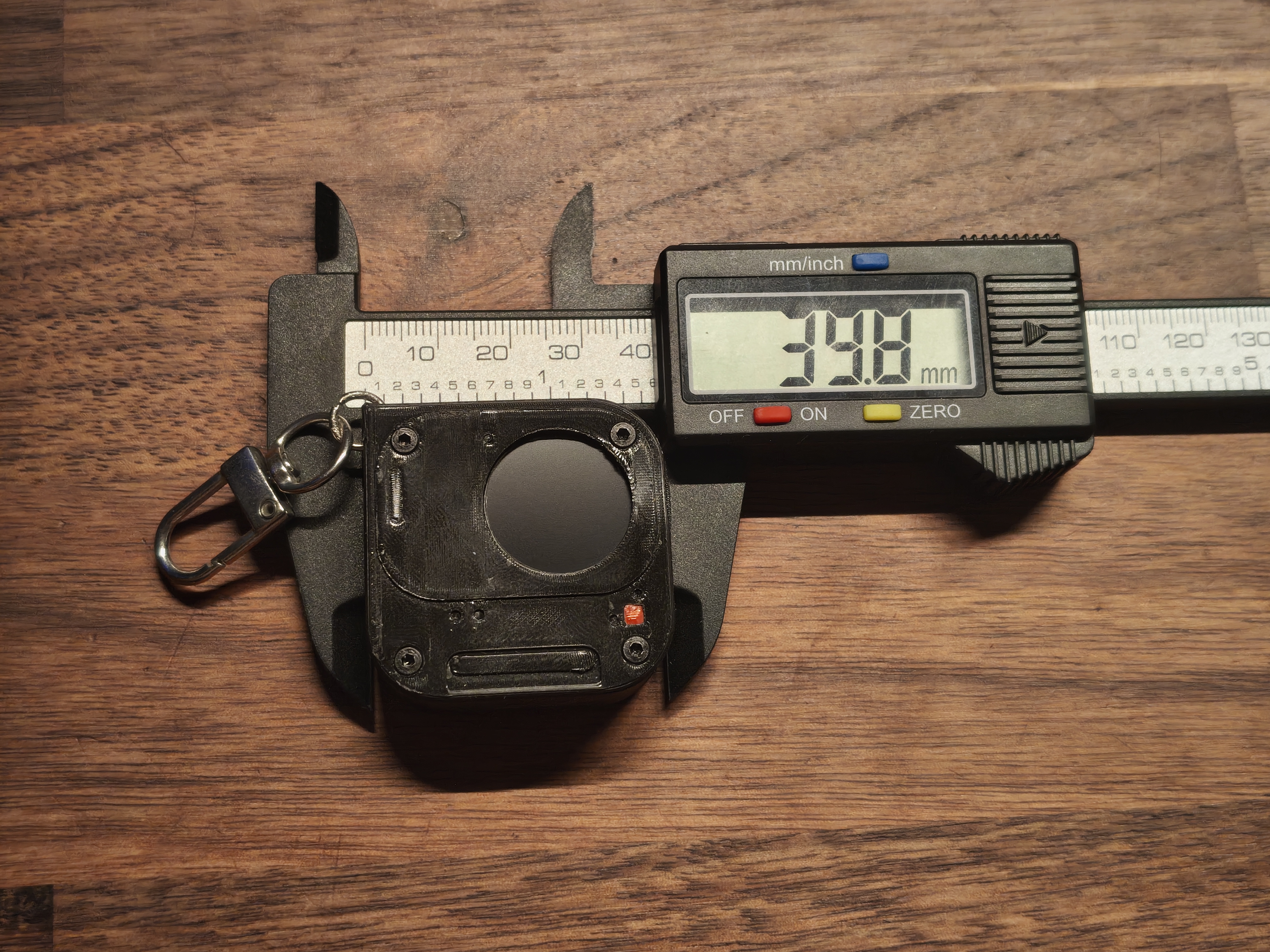 Gadget Size
Picking the board and battery
The board made this easy: a Waveshare ESP32-C3-LCD-0.71, about 17 EUR, with almost everything I needed in one coin-sized module. A 0.71 inch round IPS display (160x160, GC9D01 over SPI), an ESP32-C3 with WiFi and Bluetooth for the wireless uploads I would add later, and onboard charging (a PL4054) with a USB-C port and an exposed VBAT pad to solder a battery straight to. That last part sold it: I could skip designing power electronics and put my time into the firmware and the case instead.
For the battery I found a small round LiPo sold as a replacement cell for a Garmin Fenix watch, which suited the round shape perfectly. The label said 3.7V and 500mAh. Measured, it is closer to 300mAh. Aftermarket cells lie, and it is worth knowing that before you size your power budget around the number printed on them.
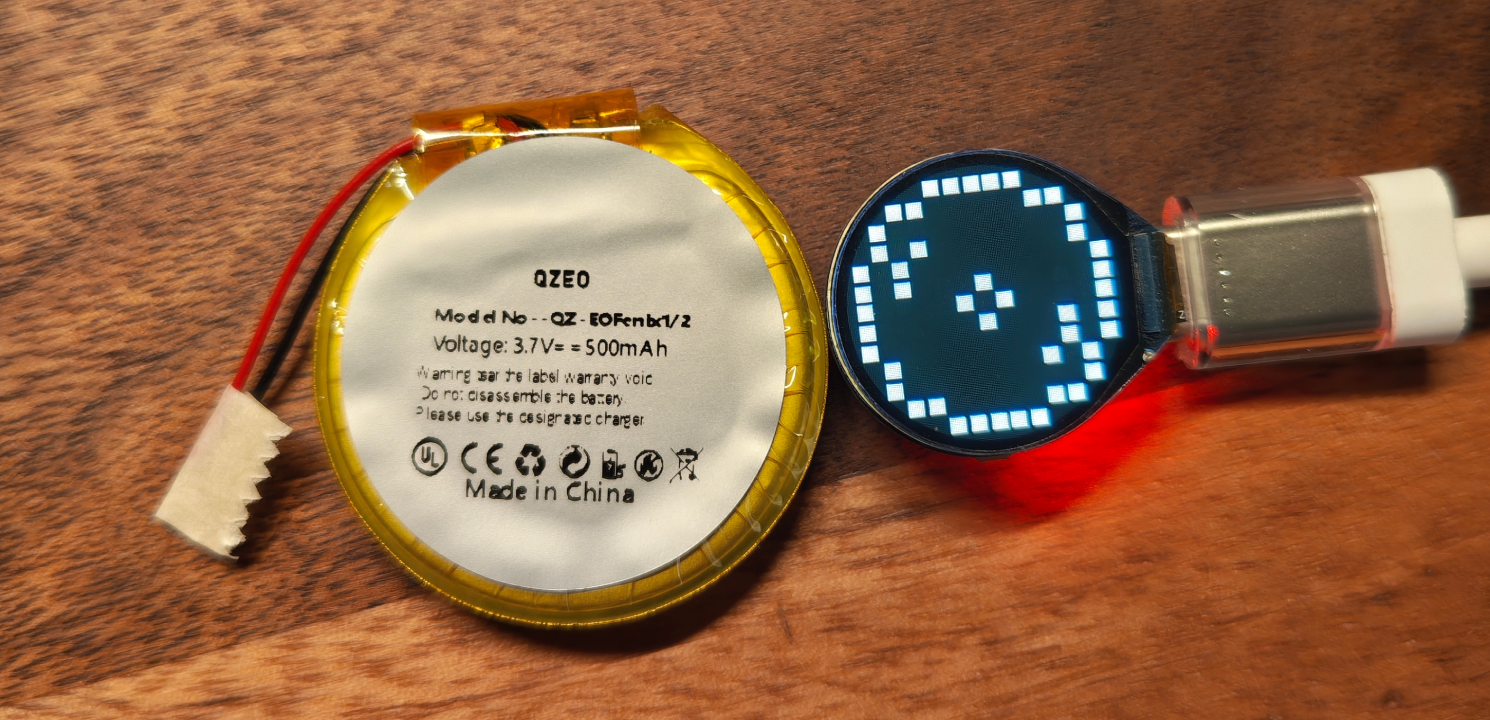 The round LiPo, next to the display already running an animation
Faking an LED matrix
Here is the trick at the centre of the whole thing. The real Glyph Matrix is hundreds of individual LEDs. I have a single round LCD. So the firmware does not drive LEDs at all, it simulates the matrix.
It keeps a flat array of brightness values, one per dot, and draws each dot as a small square on the screen. The Phone (3) layout is a 25x25 grid with 489 dots; the Phone (4a) Pro is 13x13 with 137. The firmware reads which one it is from the animation file and lays out each row to match the circular shape, so the same code renders both.
A few details that mattered more than I expected:
- Squares, not circles. At this size, drawing round dots produced ugly antialiasing fringes, so each dot is a tiny filled rectangle instead.
- Only redraw what changed. Each frame is compared against the previous one and only the dots that actually changed get repainted. Identical frames are skipped entirely.
- Draw to memory, flush once. The GC9D01 hated hundreds of scattered small writes per frame and threw coloured artifacts everywhere. The fix was to render the whole frame into a RAM framebuffer first, then push it to the display in a single burst.
On the library side I will spare you the saga: I landed on Arduino_GFX after TFT_eSPI kept crashing the chip. The display also ships with its colours inverted and rotated in odd ways, so there is a small pile of corrections to get a clean image.
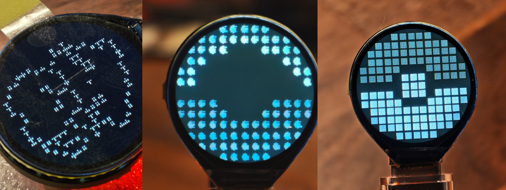 The process of accurately simulating the matrix on screen
Animations without recompiling
The first version of the workflow was miserable. Paint an animation in GlyphMatrixPaint or the Glyph Museum app, export it as JSON, run a Python script to turn it into a C header, recompile the whole sketch, flash it over USB. Every tiny tweak meant a full reflash.
So I gave the gadget WiFi. Now it boots its own access point. You connect, a captive portal drops you straight onto a web page at glyph.pin, and you drag and drop the JSON file. The browser converts it into a compact binary, uploads it, and it lands in a gallery of up to 10 animations stored on the chip itself. You can reorder them by dragging, set it to auto-rotate every few seconds, and never touch a cable.
The whole interface is plain HTML, CSS and JavaScript, gzipped down to about 5KB and baked into the firmware. No app, no account, just a browser.
 The web UI served from the gadget, showing the animation gallery and other settings
The physical build
With the electronics working on a desk, it needed a body.
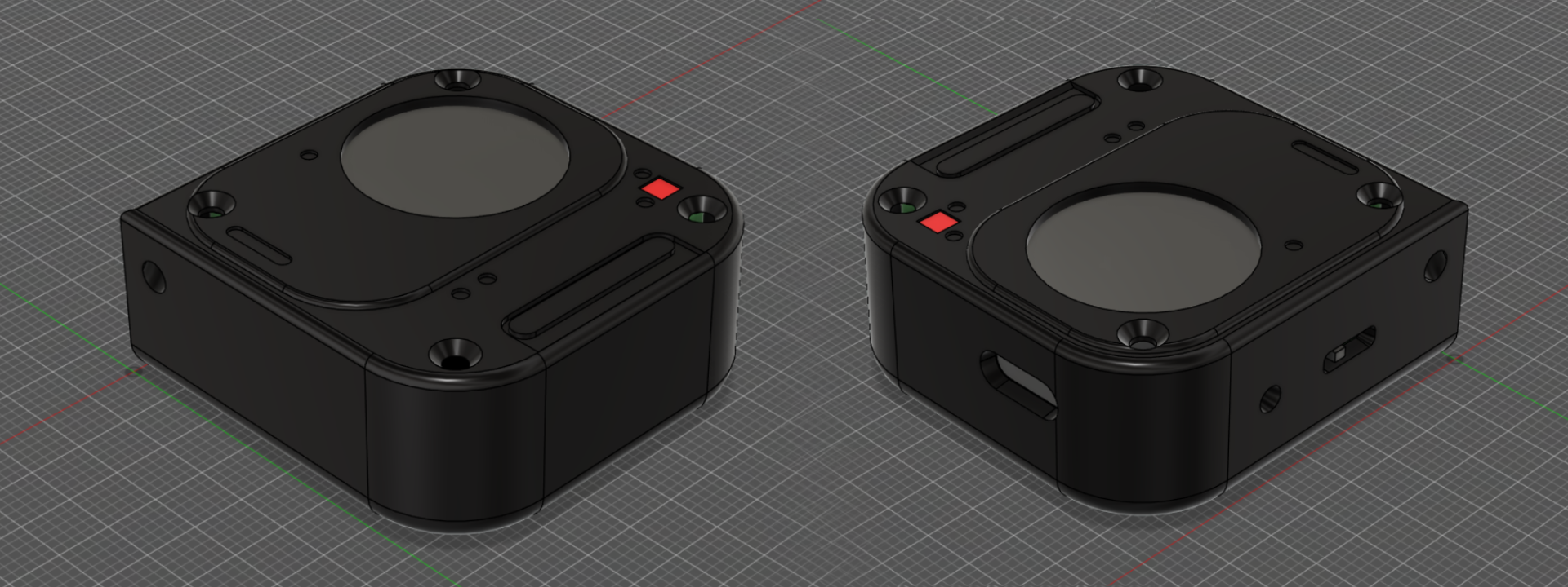
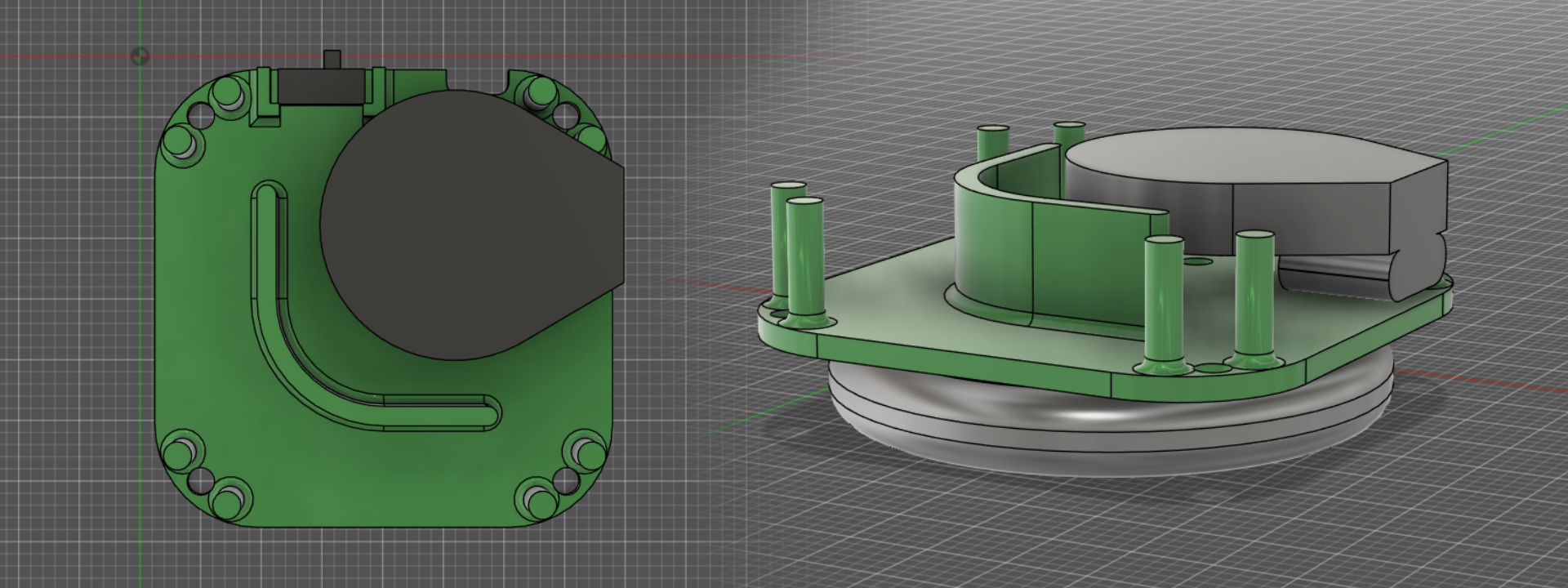
I sketched the case over and over before committing, working out where the screen, button and screws would sit on a shape barely bigger than a coin. Then it was a lot of time with digital calipers, measuring the board, the screen bezel and the battery down to fractions of a millimetre.
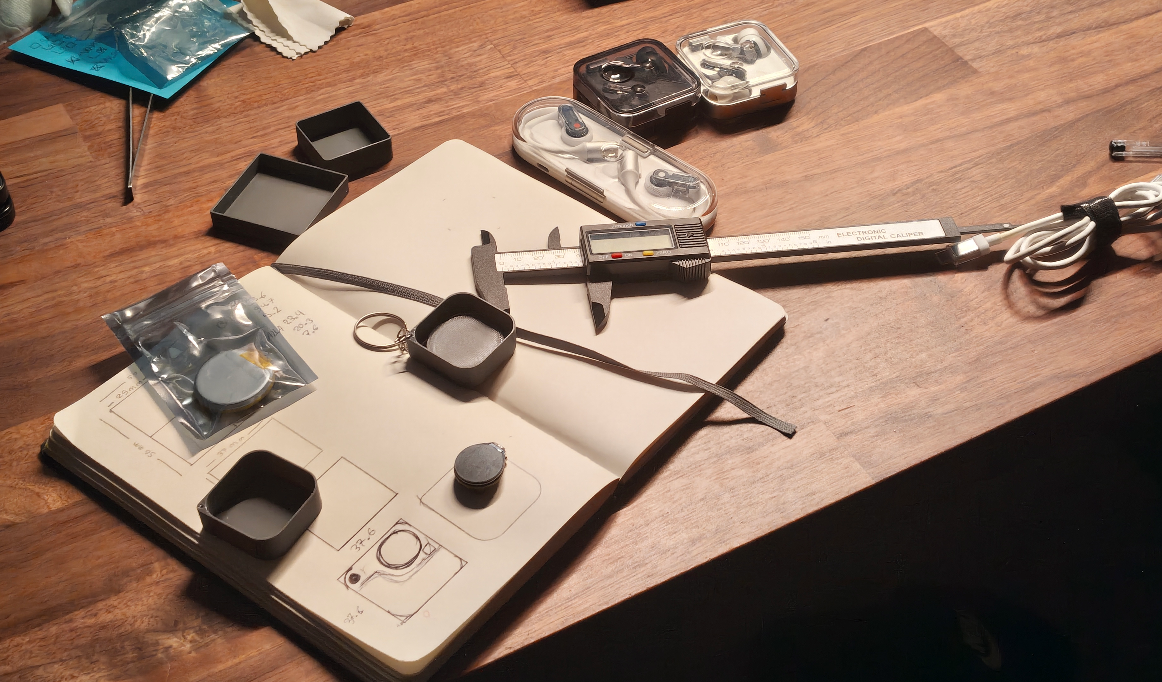 My desk in prototyping mode
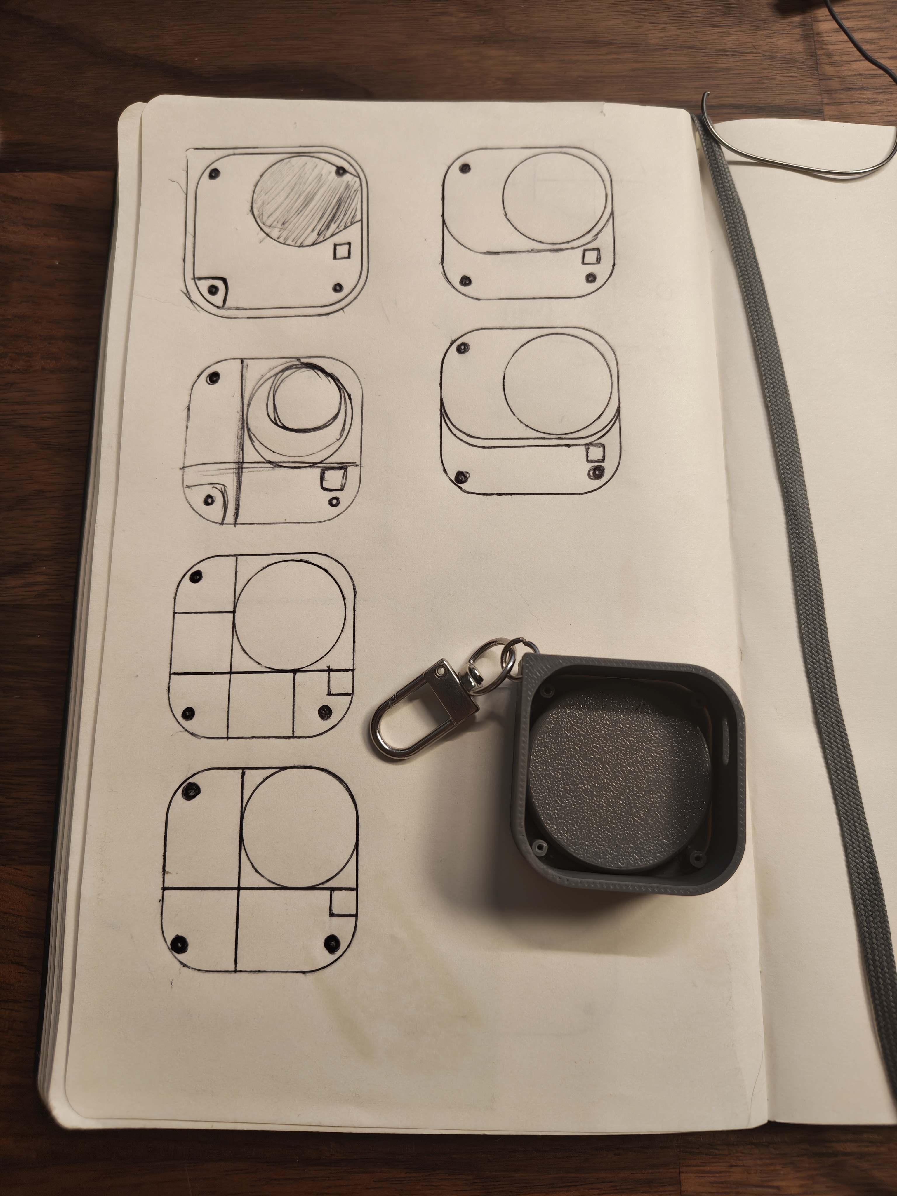 Notebook page with several case design iterations next to one of the first printed shell
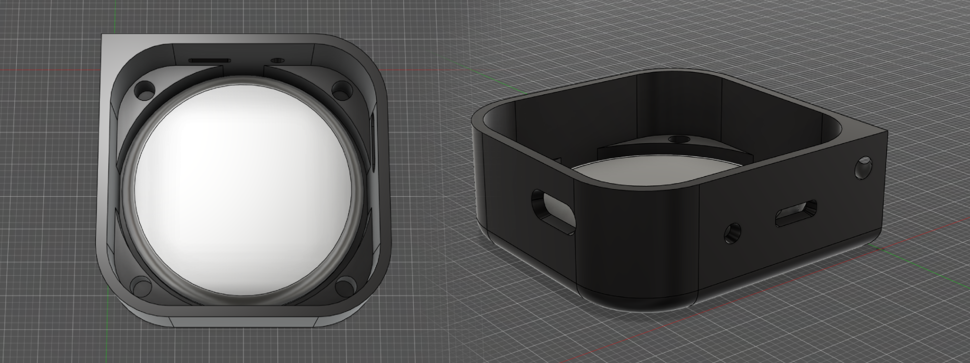
I modelled the case in FreeCAD and printed it in two pieces in black matte filament, to sit closer to the Nothing look. There is a keychain clip on one corner, and a neodymium magnet plus a badge needle glued to the back so the whole thing also works as a pin.
 Lower shell with the battery
 Base and components
Final assembled enclosure
Power, and what did not work
On a USB power meter the gadget draws about 0.6W at 5V. Not much, but on a 300mAh battery every milliamp counts, which led me down a couple of dead ends worth sharing.
Dimming the backlight. I assumed I could lower brightness on battery by PWM-ing the backlight pin. On this particular board the backlight is not PWM-dimmable, the brightness simply would not change, so I tried it, confirmed it did nothing, and reverted the code.
Deep sleep on a button hold. The obvious power saver is to deep sleep the chip and wake it with the button. The catch: the only button is on GPIO9, and on the ESP32-C3 that pin is not RTC-capable, so it cannot wake the chip from deep sleep. I pivoted to light sleep plus a restart on wake, which is not as efficient but actually works with the hardware I have.
Protecting the cell. The protection circuit on the battery only cuts power around 2.5 to 3.0V, which is hard on a LiPo over time. Cutting off earlier, nearer 3.3V, in firmware is still on the list.
None of these are glamorous, but they are the reality of squeezing a wearable onto a coin-sized board.
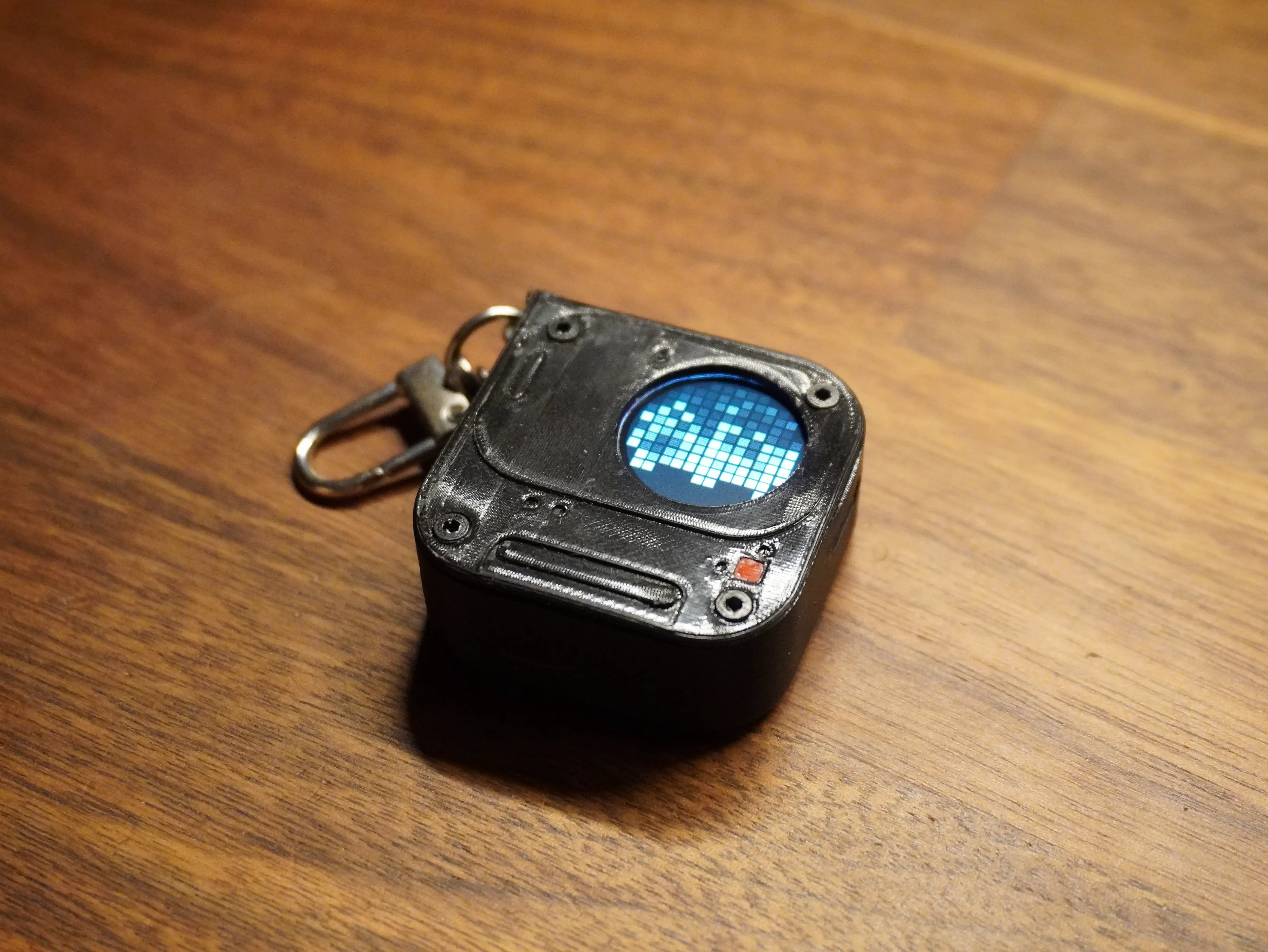
Where V0 landed
Today the gadget boots, serves its own WiFi and web page, and plays a rotating gallery of dot animations and pixel art off the battery, clipped on as a pin. Tap the button to jump to the next animation, hold it to put it to sleep. It is genuinely usable as it is.
A standalone clock and phone notifications over MQTT are the next things I want on the firmware side, but the core loop, render and manage animations on a tiny round Glyph Matrix, is done and working.
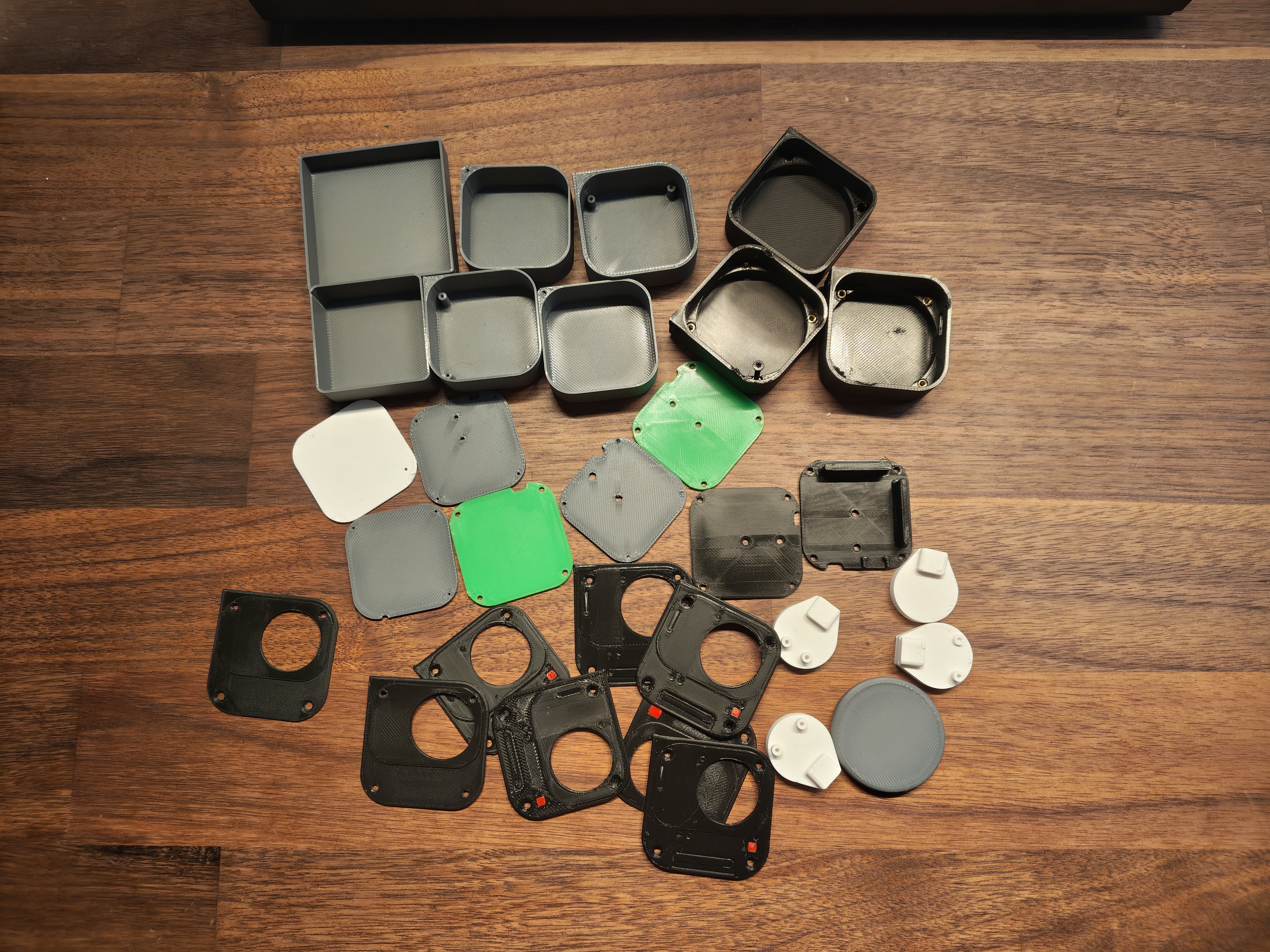 All the printed prototypes parts
The dashboard connecting and changing the animations live
What is next: V1
V0 proved the software. V1 is about making it real hardware.
I want to design a custom PCB with sensors and extra modules, to give the gadget more to actually do beyond playing animations. And I want a properly finished enclosure, CNC-cut acrylic or cast resin instead of printed PLA, so it looks like a product rather than a prototype.
For now though, V0 sits on my keychain and does the one thing I set out to build: a little piece of the Nothing Glyph Matrix that goes everywhere I do.